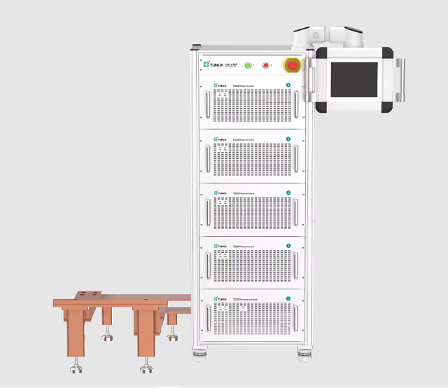
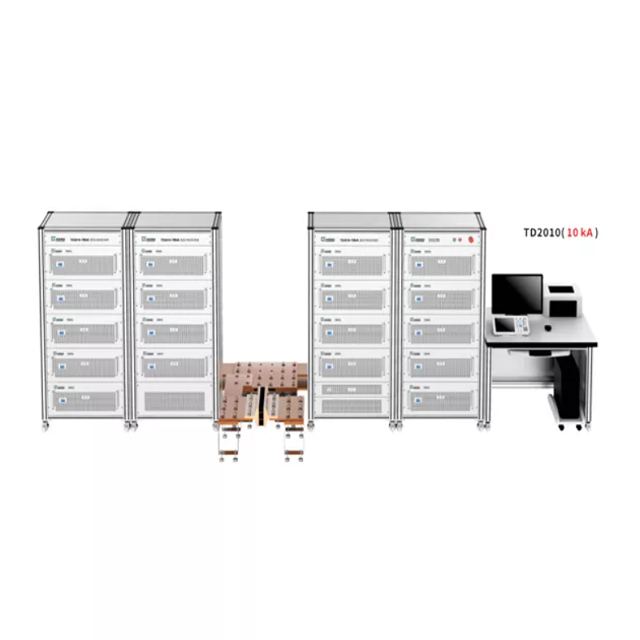
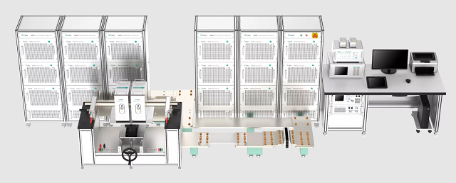
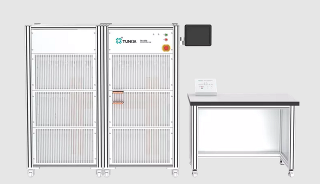
TD2010 is a set of DC high current standard source equipment, using modular design, multiple current output units in parallel can directly generate a maximum of 15 kA of high-precision DC high current. The device has high accuracy, good stability, high reliability, and supports continuous 24 hours of work. It also supports optional sensor test work to form a DC current sensor test system, can also be equipped with a special bracket and secondary voltage measurement module, easy to access DC shunt for testing.
5. Specifications
5.1 DC high current standard source
Range | Short-term stability (%/min) | Measurement uncertainty (k=2). (ppm*RD+ppm*RG)① | Maximum load voltage (V) |
0.05 | Class 0.02 | Class 0.01 | Class 0.05 | Class 0.02 | Class 0.01 |
100 A | 0.01 | 0.005 | 0.003 | 400+100 | 150 + 50 | 60 + 40 | 3.5 |
200 A | 0.01 | 0.005 | 0.003 | 400+100 | 150 + 50 | 60 + 40 | 3.5 |
500 A | 0.01 | 0.005 | 0.003 | 400+100 | 150 + 50 | 60 + 40 | 3.5 |
┆ | ┆ | ┆ | ┆ | ┆ | ┆ | ┆ | ┆ |
15 kA | 0.01 | 0.005 | 0.003 | 400+100 | 150 + 50 | 60 + 40 | 3.5 |
Note: (1) RD is the reading value, RG is the range value, the same below |
• Output range: 10 A~600 A (expandable to N*600A), 7-bit display
• Fineness: 5 ppm*RG, ripple coefficient: <0.5% @ 5 kHz or less
• Settling time: The output time to 0.01% accuracy is less than 3 s
• Protection function: open circuit protection, overload protection
5.2 DC voltage measurement
Voltage range | Resolution | Measurement uncertainty (k=2). (ppm*RD+μV) | Temperature coefficient @ (15~30)°C (±ppm*RD/°C) |
Class 0.05 | Class 0.02 | Class 0.01 | Class 0.05 | Class 0.02 | Class 0.01 |
1mV | 1 nV | 150 + 1 | 80 + 0.5 | 70+ 0.5 | < 30 | < 15 | < 15 |
10mV | 10 nV | 150 + 3 | 80 + 1.5 | 70 + 1 | < 10 | < 5 | < 5 |
100mV | 100 nV | 150 + 10 | 80 + 5.0 | 70 + 3 | < 10 | < 5 | < 5 |
1V | 1 μV | 150 + 20 | 80 + 20 | 70 + 30 | < 5 | < 2 | < 2 |
10V | 10 μV | 150 + 100 | 80 + 50 | 70 + 300 | < 5 | < 2 | < 2 |
• Measuring range: ± (100 μV~11 V), manual/automatic range switching
• Input resistance: >1GΩ; Input protection: ± 50Vpk, continuous.
5.3 Sensor power supply and output measurement (optional).
Sensor secondary signal measurement | Electro-voltage measurement range | 100 m V, 1 V, 10 V, manual or automatic shifting |
Voltage measurement range | ± (10mV~12V) |
Current measurement range | 10 mA, 1 00 mA, 1 A, manual or automatic shifting |
Current measurement range | ± (1 mA~1.1 A) |
Measurement uncertainty (k=2) | 0.002%*RD + 0.003%*RG |
Displays the number of digits | 7-digit decimal |
Temperature coefficient | 5 ppm/°C @ (0°C~40°C) |
Sensor power supply | Supply voltage | DC ± (5.0 V~50.0 V) adjustable |
Maximum load capacity | 1 A |
Measurement uncertainty (k=2) | Voltage/current: 0.2%, power: 0.5%. |
Protection features | Short circuit protection, overload protection, overtemperature protection |
AC power supply (customized) | The AC 220 V power supply can be increased according to the user's needs |
6. General Specifications
Power supply | Three-phase five-wire, AC 38 0 V ± 38 V, 50 Hz ±2 Hz |
Maximum power | N×4 kVA (N is the number of current output units). |
Working environment | 0°C ~ 50°C, (20% ~ 85%) R· H, no-condensing |
Storage environment | -20°C ~ 70°C, <85% R· H, no-condensing |
Warm-up time | 2 hours |
Device size
| 600 A module | 560 mm (W) X 560 mm (D) X 1500 mm (H) |
5 kA module | 1980 mm (W) X 756 mm (D) X 1700 mm (H) |
15 kA module | 5100 mm (W) X 2400 mm (D) (with sensor test fixture). |
Communication interface | RS232 |